To Do - Source User
1. From the Notes menus, choose File - Database - New. (or press CTRL+N)
2. In the dialog box, leave Local as the Server, and enter a Title and File Name. These can be whatever you would like. "Friends and Family", "Secondary Address Book", "Old Girlfriends", etc. The most important thing is that you choose "Personal Address Book" as the template
3. Press OK, and Notes will create the new database for you. Now we want to transfer contacts from your original Address Book, into the new one you just created. As with any change, you many want to make a backup before doing this, just to make sure you don't loose any data!
4. Open your original address book, names.nsf. Select the contacts you want to move. From the Notes menus choose Edit - Cut. (or press CTRL+X)
5. Open the new address book that you created in step #2. From the Notes menus choose Edit - Paste. (or press CTRL+V)
A secondary address book only contains Groups.
6. The personal address book database filename is "names.nsf"; the newly created "Group" address book database name can be "names2.nsf". Generally it can be found in c:\notes\data.
7. Copy "names2.nsf" to shared drive or flash drive.
To Do - Target User
1. Close Lotus Notes and all other programs related to Lotus Notes.
2. Rename names.nsf(Generally found in C:\notes\data).Dont delete it.
3. Open you notes again.It would automatically creates a new address book (names.nsf).
4. Copy "names2.nsf" from shared drive to C:\notes\data
5. Open the new address book (names.nsf) from the workspace and then open the "Group" address book("names2.nsf") by file->database->open.5.Copy the content from the "names2.nsf" to "names.nsf" address book.
References:
http://www.lotusnoteshelp.blogspot.com/2008/03/error-namesnsf-file-does-not-contain.html
http://www.alanlepofsky.net/alepofsky/alanblog.nsf/dx/secondary-directory
Friday, March 27, 2009
Cognos 8 Server System Logging
Cognos 8 Log Files
(Excerpt from Cognos 8 BI Troubleshooting Guide)
Log files help troubleshoot problems by recording the activities that take place. Operations performed in Cognos 8 are recorded in various log files for
tracking purposes. For example, during installation of Cognos 8, consult the
transfer log file to learn what activities the installation wizard performed while transferring files.
Before log files are been viewed, ensure that they contain the information that needed. The
number of log files and the information they contain are set by parameters in Cognos Connection
and in Cognos Configuration.
Use the server administration tool in Cognos Connection to learn about logging categories and
how to set the level of detail to log for each category.
For troubleshooting purposes, set the logging level to 3 or 4 to start. Level 5 should only be used after contacting Cognos Support.
For more information, see the Cognos 8 Administration and Security Guide.
Use Cognos Configuration to specify the size, number, and location of log files, and to configure
the properties of the log server. For more information, see the Cognos Configuration User Guide.
When troubleshooting, the following files will be useful:
The Transfer Log File
This file records the activities that the installation wizard performed while transferring files. The
transfer log file is located in the crn_location\instlog directory. The file name identifies the product
name, version, and build number, and includes a time stamp. The following is an example of the
file name format:
tl-CRN-8-0-0-0-20021104_0942.txt
The Transfer Summary-Error Log File
This file records the components installed, disk space information, the selections made in
the transfer dialogs, and any errors the installation wizard encountered while transferring
components. The transfer summary-error log file is located in the crn_location/instlog directory.
The file name identifies the product name, version, and build number, and includes a time stamp.
The following is an example of the file name format:
tl-CRN-8-0-0-0-20021106_1122_summary-error.txt
The Startup Configuration File
This file records configuration choices each time property settings are saved. If configuration is unable to be saved Previously saved configuration file is reverted. The backup configuration files are located in the crn_location/configuration
directory. The following is an example of the file name format:
crnstartup_200211231540.xml
The Locale Configuration File
This file records the configuration choices made in Cognos Configuration for product and
content locales, locale mapping, and currency support. If problems with language
support in the user interface or in reports is experienced, use these files to track the changes. The backup
configuration files are located in the crn_location/configuration directory. The following is an
example of the file name format:
crnlocale_200211231540.xml
The Run-Time Log File
On the applications server, he default Cognos 8 log file named crnserver.log file, or other log files that is configured to receive log messages from the log server, record information after the Cognos 8 service is started. They are located in the crn_location/logs directory. If another destination for log messages are configured, check the appropriate file or database.
Some log messages indicate problems. Most messages provide information only, but others can
help to diagnose problems in run-time environment.
The Gateway Log File
The Cognos 8 gateways record errors in the gateway log file, which is located in the
crn_location/logs directory. The gateway log file can be used to troubleshoot problems that
prevent the gateway from processing requests or from using encryption. Symptoms of these
problems are user IDs and passwords do not work and the
dispatcher is running but users receive the following error message: The Cognos BI server is
not available. The gateway log file uses the following naming format, where gateway_interface
is cgi, mod (Apache 1.3 module), mod2 (Apache 2.0 module), or isapi.
gwgateway_interface.log
The Uninstallation Log File
This file records the activities that the Uninstall wizard performed while uninstalling files. The log
file is named cognos_uninst_log.htm and is located in the Temp directory. The log file can be used to troubleshoot problems related to uninstalling Cognos 8 components.
The Silent Mode Log File
This file records the activities that Cognos Configuration performed while running in silent mode.
This log file is named crconfig_response.csv and is located in the crn_location/logs directory.
The ReportNet(R) to Cognos 8 Upgrade File
This file contains a summary of the results of an upgrade from ReportNet(R) to Cognos 8. The log file is named upgradeLog.xml and is located in the c8_location/log directory. The file is in xml format and references an xslt stylesheet. The file can be double-clicked to have it appear in the browser.
Cognos 8 Architecture

The architecture presented above reflects the Cognos 8 architecture.
Presentation Service
The presentation service handles requests for Cognos Connection, Query Studio, and Event Studio.
Report Service
The report service handles interactive requests to run reports and provides output for a user in Cognos Connection or a studio.
Report Data Service
The report data service handles requests to import Cognos report data to Microsoft Office workbooks and presentations through Cognos Office Connection.
Batch Report Service
The batch report service handles background requests to run reports and provides output on behalf of the monitoring service.
Job Service
The job service runs jobs by signaling the monitoring service to run job steps in the background. Steps include reports, other jobs, import, exports, and so on.
Monitoring Service
The monitoring service assigns a target service to handle a scheduled task. For example, the monitoring service may ask the batch report service to run a report, the job service to run a job, or the agent service to run an agent. The monitoring service will monitor the running of the task and collect and save history information for the task. The monitoring service can also take control of asynchronous service conversations on behalf of the client, such as if a user asks to run an interactive report in the background.
Log Service
The log service manages all logs generated by the dispatcher and other services. The log service can be configured to record log information in a file, a database, a remote log server, Windows Event Viewer, or a UNIX system log.
Content Manager Service
The Content Manager Service performs object manipulation functions in the content store, such as add, query, update, delete, move, and copy.
Metrics Manager Service
The Metrics Manager Service provides the Metric Studio user interface for monitoring and entering performance information.
Data Integration Service
The data integration service controls the loading of metrics data and the calculation of metrics status for scorecarding in Metric Studio.
Delivery Service
The delivery service sends emails on behalf of other services, such as the report service, job service, agent service, or data integration service.
Event Management Service
The event management service manages scheduled tasks. When a scheduled task begins to run, the event management service asks the monitoring service to begin running the task.
Agent Service
The agent service runs agents. If the conditions for an agent are met when the agent runs, the agent service asks the monitoring service to run the tasks.
System Service
The system service defines the Business Intelligence Bus API-compliant service used to obtain application-wide Cognos 8 configuration parameters. It also provides methods that normalize and validate locale strings and map locale strings to locales supported by the application.
LDAP Authentication Integration

Reporting client connects to Reporting server directly. Reporting server does user authentication first (LDAP binding). After authentication is passed, Cognos Content Store authorization applies; Available reports are displayed as a list. Different user groups have different report group access. The diagram describes processes for all user groups.
Messaging and Dispatching in the Reporting Layer
In the reporting layer, messaging occurs between the gateway, the dispatcher, and the content manager. Requests can have different levels of affinity. Affinity refers to whether a request is assigned to a specific server or whether a load-balancing mechanism can assign it to another server. Affinity between request and server ensures that requests are routed to an appropriate computer for processing. There are three types of affinity: absolute, high, and low. The cancel operation is handled with a dedicated connection and does not have an affinity type. Details regarding affinity and load balancing can be found in the ‘Cognos 8 Business Intelligence Architecture and Planning Guide’. The following extract provides and overview as well as a sample explanation on processing a report execution request.
Absolute Affinity
Absolute (control) affinity requests are always routed back to the server that processed the original request. For example, when a user cancels a running report, absolute affinity routes the cancel request back to the executing process. Absolute affinity is used to create an association between the client and the executing server to ensure that long-running requests do not time out.
Cognos 8 routes absolute affinity requests to a specific server, regardless of the load balancing used. An absolute affinity request is used with the following operations: wait, getOutput, and release.
High Affinity
High affinity requests can be processed on any of a number of servers, but resource consumption is minimized if the request is routed back to the executing process.
For example, when a pageDown command is run while reading a report, the command can be run most efficiently by using the process that served up the page that is shown. If that process is not available because the administrator shut down the computer or there was a network failure, the request is routed to another available process. The next page can still be served up, although the process will be slower.
Cognos 8 routes high affinity requests to a specific server regardless of the load balancing used. A high affinity request is used with the following operations: back, email, firstPage, forward, lastPage, nextPage, previousPage, print, render, save, and saveAs.
Low Affinity
Low affinity requests will operate just as efficiently on any computer.

When a user runs an HTML report or analysis through Cognos Connection, the following occurs:
1. The user clicks a report or analysis to run it, and the request goes through the gateway and the dispatcher to the presentation service.
2. The presentation service sends the request to the report service through the dispatcher.
3. The report service requests the report or analysis and metadata from Content Manager, through the dispatcher.
4. Content Manager sends the report or analysis XML specifications and metadata to the report service. Content Manager refetches metadata only when Cognos 8 is stopped and restarted or the model is updated and republished.
5. The report service returns one of these results to the presentation service:
- • an error page
- • a not ready page
- • a page of an HTML report or analysis
6. The presentation service sends one of these results through the dispatcher and gateway to the browser:
- • an error page
- • a wait or cancel page
- • a page of a completed HTML report or analysis in the Cognos Viewer interface
When the user presses page down or page bottom in the browser, the same path is followed again. The request has a high state of request affinity to ensure that it is routed to the same report service for additional rows of data
Load Balancing
The Cognos 8 architecture is tuned to minimize dispatch time. Cognos 8 uses network capabilities such as load-balancing routers to ensure that dispatchers and Web gateways are evenly utilized. Load balancing routers 'spray' requests across multiple Web or application servers. Although each Cognos 8 application servers has a Content Manager installed, only one is active and the other(s) are in a ‘standby’ status. Since application servers in ‘standby’ mode have more computer resource available to service report request, load balancing settings will be adjusted to direct more request to ‘standby’ servers in an effort to maintain an overall balance of resource utilization across the servers.
Gateways may be configured to recognize multiple dispatchers, however the first dispatcher listed is the primary and will be sent all request unless there is a failure. Consequently, this feature supports failover functionality but not actual load balancing.
The dispatchers are also able to balance service requests across dispatchers sharing the same content store. The dispatcher load balancing scheme is a static algorithm. A weight for each machine can be specified; a dispatcher with a weight of 2 can do twice as much work as a dispatcher with a weight of 1, and so on. Each dispatcher then simply spreads work among all the dispatchers using a weighted round-robin algorithm. Each dispatcher will accept all requests passed its way. Requests are queued by the dispatcher until executed
Load balancing is automatic in a distributed install. If there is more than one instance of a report service, dispatcher will distribute requests to all enabled instances of the service that are registered in Content Manager. The configured server Capacity determines the relative weights of the servers. Over time, a dispatcher with a capacity of 2.0 will receive twice as many requests as a dispatcher with a capacity of 1.0. In addition, Cognos 8 supports load-balancing routers.
If load-balancing routers or equivalent network technology is not used, browser requests are directed to a single Web server, as indicated in the URL. Similarly, Cognos 8 Web gateway requests are directed to a single Cognos Cognos 8 server.
Load-balancing routers and other network technologies are used to distribute network requests across several computers to ensure an even allocation of work. Load-balancing routers can be used with Cognos 8 in front of the web servers and the applications servers. The recommendation is to use them before the web servers and use the load balancing features of the dispatchers to balance the load across the dispatchers.
- Between the Client Tier: web browser or Framework Manager and Web Tier : Web Server Gateway
- Between Web Tier: Web Server Gateway and Application Tier: Report Server

Note: To ensure that requests are managed efficiently, some requests are routed back to the same report server. Cognos 8 does this automatically. The use of one or more load-balancing routers will not disrupt this process.
Cognos 8 Java Servlets and Services
Cognos 8 operates as two Java servlets running in a J2EE-compliant servlet container. The first servlet is the dispatcher. The presentation service, and the job and schedule monitoring service, are Java based and run within the dispatcher. The report service is a non-Java based application running as a child process of the dispatcher.
The second Java servlet is Content Manager, which runs in the same Java process as the dispatcher.
The main incoming port (by default 9300) is owned and managed by the servlet container or application server that routes messages to the appropriate servlet based on the URL.
Multi-Thread Management
The J2EE servlet container manages the threads (computing instructions) for each user request. This varies from a traditional C++ based application, where threads are managed by the service itself.
The Java servlet architecture provides a key advantage. If a failure occurs, only the thread associated with the request is affected. The failure does not impact the service as a whole. In other words, the affected thread will be lost, but other requests will be unaffected, and the system will continue to operate.
In addition, each report server creates and manages own threads. The report server is started and monitored by the dispatcher. If the report server fails, the dispatcher will start a new report server. The affected threads will be lost, but the system will continue to process new requests
Database Connection Management
Content Store Database
The Content Manager Service accesses the content store. Content Manager uses one database connection per request. Content Manager creates new database connections as required, pools connections, and re-uses existing connections when possible. Content Manager maintains all database connections for the duration of the Content Manager operation. The theoretical maximum number of concurrent Content Manager Requests is equal to the number of requests accepted by the Java application server.
When other Cognos 8 services are on the same computer as Content Manager, requests may be divided between Content Manager and the other services. In this case, the number of connections available to Content Manager may be less than the maximum possible connections.
The diagram below shows the use of JDBC for internal managed Cognos databases and the use of native API for reporting data sources.

The report server computer accesses the query databases. The maximum number of query database connections available can be configured to the report server computer, and the amount of time connections are retained. A cleanup thread examines the connections once per minute and any connection that has been inactive longer than the timeout value is removed.
Inactive query database connections can be claimed by a new request. This occurs when the maximum number of connections has been reached and none of the inactive connections can be used by the new request. In this case the oldest inactive connection is terminated and a new connection is created. A query database connection is only reused when the database credentials of the connection match those of the new request. When the maximum number of connections is reached, and all are active, then additional requests fail.
Thursday, March 26, 2009
Trouble Shooting - Slow Response caused by Windows Server COM+ Components - Trouble Shooting


Install Crystal Reports XI Developer
Open zip file “CrystalRptXI Install.zip”
1. Run setup.exe
1.1 Splash Screen-
Select 'English" and click "Install'
2.Welcome screen-
Click 'Next"
3. License Agreement Screen-
Check button "I Accept"
Click "Next"
4. User Information screen-Enter following at prompts.
Full Name: <Your Name>
Organization: <Your Company>
Product Key Code: < Get it from Business Objects Sales >
Click "Next"
5. Select Installation Type screen-
Check button "Typical"
Enter following at prompts.
Destination Folder: "e:\program files\business objects\"
Common Files Folder: "e:\program files\common files\business objects\3.0\"
Click "Next"
6. Start Installation screen.
Click "Next"
Note: Install check disk for space. If not enough disk space you will be prompted. Adjust space and proceed"
7. Crystal Reports Install in progress screen.
Wait until finished
If Prompted for Disk 2 - Click "OK"
8. Register Now screen-
Don't register!
Click "Register Later"
9. Crystal Reprots XI Installed screen -
UNCheck button "Check for Updates"
Click "Finish"
Main software Install is done.
OK - Now there are updates. Perform in this order.
Perform XI SP2 Install:
10. Run “crXIwin_sp2.exe” self extracting zip
11. Winzip Self-Extractor “This File will” screen -
Click “OK”
12. Winzip Self-Extractor - crXIwin_sp2.exe screen-
Enter following at prompts.
Unzip to folder: E:\Program Files\Business Objects\Crystal Reports 11\Patches\SP2
Keep Overwrite? And When done checked.
Click “Unzip”
Wait……
13. Winzip Extractor “17 files unzipped” screen -
Click “OK”
Install starts….
14. Choose Setup Screen -
Click “OK”
Run crXIwin_mhf.exe
Configure IIS to be a Smart Host for Exchange Server
Step 1: Verify the Installation of the SMTP Service
In Control Panel, open Add/Remove Programs, click Add/Remove Windows Components. Click the Internet Information Services (IIS) component, click Details, and then verify that the SMTP Service check box is selected.
If it is not selected, click to select it, click OK, and then follow the installation directions that are displayed.
Step 2: Configure the SMTP Service to Relay for Internal Domains
Depending on the scenario, it may be necessary to configure the SMTP service to relay inbound messages for your internal domains.
1. Click Start, point to Programs, click Administrative Tools, and then click Internet Services Manager.
2. Expand the tree under the server name, and then expand the Default SMTP Virtual Server. By default, you should have a Local (Default) domain with the fully qualified domain name of the server.
3. Configure the domain for inbound:
a. Right-click the Domains icon, click New, and then click Domain.
b. Click Remote, click Next, and then type the forwarder.yourcompany.com in the Name box. Click Finish.
Configure the domain for relay
1. In the properties for the domain that you just created, click to select the Allow the Incoming Mail to be Relayed to this Domain check box.
2. If this is being set up for a internal domain, you should specify the server that receives e-mail for the domain name by the IP address in the Route domain dialog box.
3. Click the forward all e-mail to smart host option, and then type the IP address of the server that is responsible for e-mail for that domain in square brackets.
Note: Typing the IP address of the server in brackets is necessary so that the server recognizes this is an IP address and not to attempt a DNS lookup.
Step 3: Specify the Hosts That You Want to Openly Relay to All Domains
Note:
Anyone can send to the domains that you specified in Step 2.
This step is for hosts, which are most likely your internal servers that would need to send to all domains on the Internet. It is not recommended to not have any restrictions because anyone can use your server as an open relay. It is recommended to only allow the minimum, necessary hosts to openly relay to all domains. To do so:
1. Open the properties of the Default SMTP Virtual Server.
2. On the Access tab, click Relay.
3. Click Only the list below, make sure the list is empty. Check the checkbox before “Allow all computers which successfully authenticate to relay, regardless of the list above”.
Install and Configure the Oracle 10g ODBC driver on Windows 2003 Server
Verify MDAC version 2.8 (use comcheck.exe).
If less than 2.8, install MDAC 2.8 by using Windows 2003 Server CDs.
Run CC_Pkg.exe
Install it in E:\Program Files\CompChecker
Run Component Checker
Make sure MDAC has version 2.8 and up
Setup Oracle ODBC and Provider for OLE DB drivers. Install or update TNSNAMES.ORA in E:\Program Files\\Network\Admin folder.
Install Oracle Client including ODBC and Provider for OLEDB
Open 10g_win32_client.zip
A. Run Setup.exe.
B. Oracle Universal installer screen.
Name: OraClient10g_hisrep
Path: E:\Oracle\Product\10.1.0\Client_hisrep
Chose “Administrator” option
Click ‘Next”
1. At Welcome Screen
-Leave ‘Typical’ button unchecked.
2. Select Naming Methods screen.
- Select ‘Local Naming’ option and > to ‘Selected Naming’ side.
- Click ‘Next’
3. Service Name screen.
- Enter sidname: hisrep
- Click ‘Next’
4. Select Protocols screen.
- Select TCP
-Click ‘Next”
5. TCP/IP Protocol screen.
- Host Name: hisreppldb.iweb.gm.com
- Keep ‘Use standard prot number of 1521.
- Click ‘Next”
6. Test screen.
- Keep ‘Yes, perform a test checked.
- Click ‘Next’
7. Net Service Name screen.
- Net Service Name: hisrep
- Click ‘Next’
8. Connect Test/Logon screen.
- Username: Medgate_v60_app
- Password: medgate60
- Click ‘OK’
9. Another Net Service Name? screen.
- Leave ‘No’ checked.
- Click ‘Next”
10. Net Service configuration Done screen.
- Click ‘Next’
11. Naming Methods configuration Done screen.
- Click ‘Next’
12. Done ‘OracleNet Configuration Complete’ screen.
- Click ‘Finish’
13. End of Installation screen.
- Click ‘Exit’
- Do you Really want to exit? prompt
- Click ‘Yes’
Verify ODBC driver.
Create new DSN source.
Go to Start->Administrative Tools->Data Source (ODBC)
Click “System DSN” Tab
Click “Add” button
Select the driver: “Oracle in OraDB10g_xxx”
Click “Finish”
Configure the Oracle ODBC Driver:
Data source name = <your_data_source>
Description = Oracle database
TNS Service name = <your_service_name>
UserID = <user_id>
TEST the database connection by click “Test Connection” button
Make sure it can establish connection. The connection will be used for other install components.
If less than 2.8, install MDAC 2.8 by using Windows 2003 Server CDs.
Run CC_Pkg.exe
Install it in E:\Program Files\CompChecker
Run Component Checker
Make sure MDAC has version 2.8 and up
Setup Oracle ODBC and Provider for OLE DB drivers. Install or update TNSNAMES.ORA in E:\Program Files\
Install Oracle Client including ODBC and Provider for OLEDB
Open 10g_win32_client.zip
A. Run Setup.exe.
B. Oracle Universal installer screen.
Name: OraClient10g_hisrep
Path: E:\Oracle\Product\10.1.0\Client_hisrep
Chose “Administrator” option
Click ‘Next”
1. At Welcome Screen
-Leave ‘Typical’ button unchecked.
2. Select Naming Methods screen.
- Select ‘Local Naming’ option and > to ‘Selected Naming’ side.
- Click ‘Next’
3. Service Name screen.
- Enter sidname: hisrep
- Click ‘Next’
4. Select Protocols screen.
- Select TCP
-Click ‘Next”
5. TCP/IP Protocol screen.
- Host Name: hisreppldb.iweb.gm.com
- Keep ‘Use standard prot number of 1521.
- Click ‘Next”
6. Test screen.
- Keep ‘Yes, perform a test checked.
- Click ‘Next’
7. Net Service Name screen.
- Net Service Name: hisrep
- Click ‘Next’
8. Connect Test/Logon screen.
- Username: Medgate_v60_app
- Password: medgate60
- Click ‘OK’
9. Another Net Service Name? screen.
- Leave ‘No’ checked.
- Click ‘Next”
10. Net Service configuration Done screen.
- Click ‘Next’
11. Naming Methods configuration Done screen.
- Click ‘Next’
12. Done ‘OracleNet Configuration Complete’ screen.
- Click ‘Finish’
13. End of Installation screen.
- Click ‘Exit’
- Do you Really want to exit? prompt
- Click ‘Yes’
Verify ODBC driver.
Create new DSN source.
Go to Start->Administrative Tools->Data Source (ODBC)
Click “System DSN” Tab
Click “Add” button
Select the driver: “Oracle in OraDB10g_xxx”
Click “Finish”
Configure the Oracle ODBC Driver:
Data source name = <your_data_source>
Description = Oracle database
TNS Service name = <your_service_name>
UserID = <user_id>
TEST the database connection by click “Test Connection” button
Make sure it can establish connection. The connection will be used for other install components.
Turn on ASP support in IIS (Windows 2003 server)
Turn on ASP support in IIS Administration.
Open IIS Manager
- click Web Sites
- open
- Right click
- Select Properties
- Select Tab ‘Home Directory”
- Click ‘Configuration Button”
- Verify that .ASP and .ASPX are in ‘Application Extensions’ list. Otherwise add them.
- Click OK to close.
Open IIS Manager
- click Web Sites
- open
- Right click
- Select Properties
- Select Tab ‘Home Directory”
- Click ‘Configuration Button”
- Verify that .ASP and .ASPX are in ‘Application Extensions’ list. Otherwise add them.
- Click OK to close.
Configure SMTP on IIS (Windows 2003)
Step 1: Verify the Installation of the SMTP Service
In Control Panel, open Add/Remove Programs, click Add/Remove Windows Components. Click the Internet Information Services (IIS) component, click Details, and then verify that the SMTP Service check box is selected.
If it is not selected, click to select it, click OK, and then follow the installation directions that are displayed.
Step 2: Configure the SMTP Service to Relay for Internal Domains
Depending on the scenario, it may be necessary to configure the SMTP service to relay inbound messages for your internal domains.
Click Start, point to Programs, click Administrative Tools, and then click Internet Services Manager.
Expand the tree under the server name, and then expand the Default SMTP Virtual Server. By default, you should have a Local (Default) domain with the fully qualified domain name of the server.
Configure the domain for inbound:
Right-click the Domains icon, click New, and then click Domain.
Click Remote, click Next, and then type the forwarder.gm.com in the Name box. Click Finish.
Configure the domain for relay
In the properties for the domain that you just created, click to select the Allow the Incoming Mail to be Relayed to this Domain check box.
If this is being set up for a internal domain, you should specify the server that receives e-mail for the domain name by the IP address in the Route domain dialog box.
Click the forward all e-mail to smart host option, and then type the IP address of the server that is responsible for e-mail for that domain in square brackets. IP of forwarder.yourcompany.com is:
[168.208.12.12]
Note: Typing the IP address of the server in brackets is necessary so that the server recognizes this is an IP address and not to attempt a DNS lookup.
Click OK.
Install SMTP service under Windows Server 2003
The version of Microsoft IIS that ships with Windows 2003 contains a service that you can use to deliver mail using SMTP. To install this SMTP service, perform the following steps:
1. Start the Control Panel Add/Remove Programs applet.
2. Click Add/Remove Windows Components.
3. After the Windows Components Wizard appears, select Applications Server and click Details.
4. Select Internet Information Services (IIS), then click Details.
5. Select SMTP Service, then click OK as this figure shows.
6. Continue to click OK to close all other dialog boxes until you're back at the Windows Components Wizard page, then click Next.
Windows 2003 will copy the files required for the SMTP service (you might be prompted to insert the installation CD-ROM) and configure the service. You can also install the SMTP service through the E-mail Services tool, which is a POP3 component that automatically installs SMTP. Windows 2003 configures the SMTP service to use a default server, and you can use the IIS Manager to modify the server settings.
Determine MDAC version
Determining which version of MDAC is installed on a computer at any given time presents certain difficulties because individual MDAC files may have been replaced by an errant installer, which complicates the situation. Component Checker is probably the most useful tool that is available for verifying MDAC installations. Component Checker is available for download from Data Access and Storage Developer Center MDAC Downloads.
Install and Use the Component Checker Tool
The most reliable way to determine which version of MDAC is installed is to compare the version number of each MDAC DLL file to a list of the DLL files that are shipped with each MDAC version. The Component Checker can help you to do this. It checks the files on the computer, compares them to a list from each version of MDAC, and reports the closest match.To install Component Checker, follow these steps:
1. Browse to the following Microsoft Web site:
http://www.microsoft.com/downloads/details.aspx?FamilyId=8F0A8DF6-4A21-4B43-BF53-14332EF092C9&displaylang=en (http://www.microsoft.com/downloads/details.aspx?FamilyId=8F0A8DF6-4A21-4B43-BF53-14332EF092C9&displaylang=en)
2. Click the link to download Component Checker. When you are prompted by the browser, save Cc.exe (a self-extracting executable file) to the desktop.
3. On the desktop, double-click Cc.exe; this extracts the Component Checker files and installs to the default location, C:\Comcheck.
To use Component Checker to check the MDAC version, follow these steps:
1. From the Start menu, click Run.
2. In the Open text box, type c:\comcheck\comcheck.exe and then click OK.
3. In the Component Checker - Choose Analysis Type dialog box, select Perform Analysis of your machine and automatically determine the release version, and then click OK.
4. The program attempts to identify the MDAC version on your computer by scanning all of the core MDAC files and registry settings. This process normally takes several minutes. When finished, you should receive the following message:
The MDAC version that is closest to the version on your computer is 'XXXX'.
5. Click OK.
6. A summary of the Component Checker scan appears. Note that the Dir, FileDescription, and FileSize errors can be safely ignored.
Check the Version Information Stored in the Registry
Although not the most reliable way to check the MDAC version, checking the registry for the version information is an easy way to double-check this information (if you are not experiencing any MDAC-related issues).The version information is found in the following key:
HKEY_LOCAL_MACHINE\Software\Microsoft\DataAccess\FullInstallVer
To check the registry, follow these steps:
1.On the Start menu, click Run.
2.In the Open text box, type regedit and then click OK; this starts Registry Editor.
3.In the Navigation pane, drill-down to the following path:
HKEY_LOCAL_MACHINE\Software\Microsoft\DataAccess
4.In the Details pane, look in the Name column for FullInstallVer and Version. Each of these keys will have corresponding version information in the Data column.
5.When finished, click Exit on the Registry menu to close Registry Editor.
Enterprise Master Data Management (MDM)
Introduction
•Goal: Single place where all common master data in an organization is stored and managed. The data would be accurate, consistent, and maintained in a coherent and secure manner.
•Provides a consistent understanding and trust of master data entities
•Provides mechanisms for consistent use of master data across the organization
•Is designed to accommodate and manage change
Why MDM
•Cross-LOB Perspective (Investments, Loans, Deposits; sees data as critical to operations, not see value in sharing)
•Cross-Channel Perspective (dist. Channel- Partner, Internet, Branch; different solutions->account-centric->customer centric))
•Cross-Business Subdomain Perspective (Case history, Contact preference, Party; different scope)
•Cross-Application/Technology Perspective (packaged apps; variance in technoical platform
•Mergers and Acquisitions
MDM System
•Master Data Domains – Recognition of CDI and PIM. Three primary domains: party, product and account
•Methods of Use – Collaborative Authoring (users & systems to reach agreement), Operational (providing stateless services), Analytical (trusted data source, key function or analytics)
•System of Record (read-only) vs. System of Reference
•Consistency of Data – Absolute Consistency (consistent all the time), Convergent Consistency
•Implementation Styles – Consolidation Implementation (gold source); Registry Implementation (for read-only); Coexistence Implementation (master in many locations); Transactional Hub Implementation.
•Categorizing Data – Metadata, Reference Data, Master Data, Transaction Data, Historical Data
Collaborative MDM (New Product Introduction example)
•1. Receive Notification of New Item
•2. Create Draft Item
•3. Classify Item and Assign SKU
•4. Define Item Properties
•5. Define Marketing Properties
•6. Assign Item to Locations
•7. Define Finance Properties
•8. Approve Product Definition
Operational MDM (OLTP)- New Account Opening
•1. RECORD Arrangement Request
•2. ANALYZE Customer RElationship
•3. ANALYZE Arrangement Request
- APPLY Product Policy
- APPLY Credit Rating Scale
- FORECAST Arrangement Risk
- OFFER Arrangement
Implementation Style
•Consolidation
•Registry
•Coexistence
•Transactional Hub
Data Category
•Metadata
•Reference data
•Master Data
•Transactional Data
•Historical Data
Business Benefits of MDM
•Consistent Understanding and Trust of Master Data Entities – Accuracy, Completeness, Consistency, Timeliness, Relevance, Trust
•Consistent Use of Master Data Across the Organization – Cost Savings and Efficiencies, Regulatory Compliance
•Accommodate and Manage Change – Reducing Time to Market, Revenue Enhancement and Other New Opportunities, Ability to Rapidly Innovate, Product or Service Innovation, Process Innovation, Market Innovation, Supply Chain Innovation, Accommodating Mergers and Acquisitions, Introduction of New Requirements
An SOA Enabler (SOA Architecture)
•Layer 1 – Consumers
•Layer 2 - Business Process (Composition, Choreography, Business State Machine, Orchestration)
•Layer 3 – Services (atomic and composite)
•Layer 4 – Service Components
•Layer 5 – Application Services
•Layer 6 – Data Repositories & Information Services
•Layer 7 – Integration (Enterprise Service Bus)
•Layer 8 – Quality of Service (Security, Management, Monitoring)
•Layer 9 - Governance
Characteristics of SOA services (also for MDM)
•Service reuse
•Service granularity
•Service modularity and loose coupling
•Service composability
•Service componentization and encapsulation
•Compliance with standards (both common and industry-specific)
•Services identification and categorization
•Provisioning and delivery
•Monitoring and tracking
Information as a Service: Characteristics
•Definition – The structure and the semantics of the information needs to be well defined and commonly available
•Quality – integrity of the data needs to be ensured for retrieval and update
•Governance – Changes to the service and the underlying information need to be governed in a uniform and consistent manner
MDM Reference Architecture
•Conceptual Level
•Logical Level
•Physical Level
Architecture Pattern
•Process-Focused Application Integration (integration of applications)
•Information-Focused Application Integration (synchronize master data among MDM hub and underlying legacy systems)
•MDM Hub Patterns (style of MDM deployment)
MDM Ref – Key Functional and Technical Capabilities
•Master Data Lifecycle Mgmt Capability – from created to no longer required; group and define hierarchies; flexible mapping; define master data hierarchies, relationships, groupings; versioning; model multiple taxonomies; authoring; security; audit;
•Data Quality Mgmt Capability – analysis & profiling; standardization, data validation, data cleansing logic; Data reconciliation; data governance; measure the staleness of data
•Master Data Harmonization Capabilities – Integration (messaging, service invocation, batch, ETL, FTP); error-handling; support high-volume transaction
•Analysis and Insight Capabilities – discover insightful relationships; improve business decision; access structured and unstructured information; manage the state of a process; configure event management services
Conceptual Architecture
•Framework to manage and maintain master data
•Scalable, highly available, adaptive architecture
•Coordinate, manage the lifecycle of master data across the enterprise
•Accurate critical business information available as a service
•Cleanse data, improve the quality and consistency of master data
•Make master data active by detecting events and generating operations to manage master data
•enable the ability to implement solutions
MDM Solution – Key architecture building blocks
•Third-Party Data Service Provider
•Process Manager to choreograph
•Connectivity and Interoperability Layer
•MDM Services and Master Data Repository
•Information Integration Services
•Identity Analytics
MDM Solution – Architecture Principles
•Provide ability to decouple information from app & process
•Available as a strategic asset for enterprise
•Authoritative source for master data (manage integrity, control distribution in a standardized way)
•On an architectural framework and reusable services
•Based on industry-accepted open computing standards
•Provide flexibility to accommodate changes
•Highest regard for preserving the ownership of data, integrity and security of data
•Ability to incrementally implement a MDM Solution
MDM – Logical Architecture Components
•Interface Services
•Lifecycle Management Services
•Hierarchy and Relationship Mgmt Services
•Master Data Mgmt Event Mgmt Services
•Authoring Services
•Data Quality Mgmt Services
•Base Services
•Master Data Repository
MDM – Information Risk Analysis
•Identifying the information assets
•Assigning value to each asset
•Identifying each asset’s vulnerabilities and associated threats
•Calculating the risk for the identified assets
•Evaluating different countermeasures in terms of costs and reduction of risk they provide
•Recommending the appropriate countermeasures
MDM – Security and Privacy: Types of IT Risks
•Operational risks – failures in business process; denial of service attack;
•Regulatory and Compliance risks – meet business processes; adequately protecting sensitive data
•Reputational Risks -
MDM – Information Risk Management
•Risk Analysis for MDM
•Security Control Selection and Implementation
MDM – Identifying MDM Assets
•Sources of master data
•Master data itself
•Consumers of master data
•Other related assets
MDM – Security Consideration
•Policy
•Confidentiality
•Integrity
•Identity
•Authentication
•Authorization
•Audit
•User Registry
•Identity provisioning
•Identity token
•Identity mapping
•Identity Propagation
•Reverse Proxy
MDM – Security Considerations
•Identity Propagation, Mapping & Provisioning – Business (Trust Mgmt, Identity and Access (Authorization) Mgmt); Technical (Identity & Authentication Service, Policy Mgmt)
•Authorization – Business (manage identities, roles and groups); Technical (standards-based to handle specifying, distributing & enforcing authorization policies.
•Audit – Business (comply with policies & reports illustrating how well relative to policies; Technical (audit events, real-time and post-processing events reporting
•Data Protection – Business (describe business object level how master data should be protected); Technical (encryption, SSL, WS-Security)
Logical SOA Security Architecture
•Business Security Services tier
•Security Policy Mgmt tier
•IT Security Service tier
Security Enablers
•Cryptography
•Key Management
•Hardware key Storage
•Cryptographic Hardware
•Malware Protection
•Isolation
•Firewalls
•Intrusion Detection
•Intrusion Prevention
•Time
•Security Event and Incident Mgmt (SEIM)
Policy Management
•Policy abstraction level
•Policy management lifecycle
•Policy Domains
Identity propagation
•Security Token Service (STS)
•SAML token for security token format
Authentication Services
•WS-Trust Security Token Service (STS)
Authorization Services
•Service Consumer
•MDM SOA Services Layer
•MDM Services Implementation
•Master Data Repositories
Oracle 8.1.6 Recovery Manager (RMAN)
Overview
•Command-line and Enterprise Manager-based tool
•Optimize performance & space consumption
•Integrate with Oracle Secure Backup
•Free dependency on OS and SQL*Plus
Functional Components
•Target DB to be backed up
•RMAN client
•A flash recovery area (disk location)
Backup and restore on Windows (32bit)
•Run run_rman.bat (can be added to schedule tasks list)
•Log File (C:\Database_Migration\RMAN\ORCL81_.log
RMAN – Files
•Run_rman.bat – main batch script
•run_sql.txt: - sql script for backup controlfile to trace
•rman_cmf.txt: rman script for backup database and old archived logs
•run_bak_ctl.txt: sql script for backup controlfile
•restore_steps.txt:steps for restore whole database from backup files
Steps to run scripts
•Step1. delete old backup files.
•Step2. create controlfile trace file and then copy it to the backup folder
•Step3. rum rman backup scripts
•Step4. using winrar compress the backup files (if winrar is available)
Parameters to be modified
•paths in run_rman.bat, rman_cmf.txt, run_bak_ctl.txt
•NowDate, Month, Day definition in run_rman.bat according to your windows system.
•winrar in run_rman.bat. You may need add the path of winrar to system path or use absolute path
If Error ORA-19602 is encountered
•ORA-19602: cannot backup or copy active file in NOARCHIVELOG mode
•C:\>SVRMGRL
•SVRMGR>connect internal
•SVRMGR>shutdown immediate
•SVRMGR>startup (if error, try ‘mount’)
•SVRMGR>alter database archivelog;
•
•SVRMGR>startup
Recover database
•Launch CMD screen (db is mount)
•C:>set oracle_sid=GEMSDB81
•C:>sqlplus /nolog
•SQL>connect / as sysdba
•Command-line and Enterprise Manager-based tool
•Optimize performance & space consumption
•Integrate with Oracle Secure Backup
•Free dependency on OS and SQL*Plus
Functional Components
•Target DB to be backed up
•RMAN client
•A flash recovery area (disk location)
Backup and restore on Windows (32bit)
•Run run_rman.bat (can be added to schedule tasks list)
•Log File (C:\Database_Migration\RMAN\ORCL81_
RMAN – Files
•Run_rman.bat – main batch script
•run_sql.txt: - sql script for backup controlfile to trace
•rman_cmf.txt: rman script for backup database and old archived logs
•run_bak_ctl.txt: sql script for backup controlfile
•restore_steps.txt:steps for restore whole database from backup files
Steps to run scripts
•Step1. delete old backup files.
•Step2. create controlfile trace file and then copy it to the backup folder
•Step3. rum rman backup scripts
•Step4. using winrar compress the backup files (if winrar is available)
Parameters to be modified
•paths in run_rman.bat, rman_cmf.txt, run_bak_ctl.txt
•NowDate, Month, Day definition in run_rman.bat according to your windows system.
•winrar in run_rman.bat. You may need add the path of winrar to system path or use absolute path
If Error ORA-19602 is encountered
•ORA-19602: cannot backup or copy active file in NOARCHIVELOG mode
•C:\>SVRMGRL
•SVRMGR>connect internal
•SVRMGR>shutdown immediate
•SVRMGR>startup (if error, try ‘mount’)
•SVRMGR>alter database archivelog;
•
•SVRMGR>startup
Recover database
•Launch CMD screen (db is mount)
•C:>set oracle_sid=GEMSDB81
•C:>sqlplus /nolog
•SQL>connect / as sysdba
SOA for Business Developer
SOA for Business
•Open Standards
•Structure of a SOA Application – composed largely of services (Integration Services, Business Services, Data-Access Services)
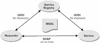
•Web and Binary-Exchange Services – WSDL, SOAP, HTTP
•Presentation Services – Portlet, HTML,
•Runtime Products – security, service allocation, service composition, logging
•Loose Coupling
•Service Registry
•Service Level Agreements
Service Aspects
•Service Implementation - Logic
•Elementary access details – Location, binding, protocol, formatting
•Contract – interface and Quality of Service
Message Exchange Patterns
•One-way pattern – (fire-and-forget)
•Request-response pattern – (in-out)
•Notification pattern – (out-only)
•Solicit-response pattern – (out-in)
•Synchronous and Asynchronous Communication
•Callbacks – (Request and callback)
Quality of Service
•Reliability guarantees- availability, throughput, response time and probability, assured message
•Security mechanisms – Authentication, authorization, confidentiality, integrity, non-repudiation, attack protection
•Service coordination, including transaction control – Orchestration, Choreography
•Runtime update of address, binding, and message content – flow of traffic change, message reformat, send message to destination other than the requester
Process Steps
•Analyzing a Business Process
•Identifying Problems with current Process
•Communicating the Assumptions in Writing
•Isolating Services
•Creating the application
XML Schema
•Data Type – primitive, derived, simple, complex
•Purposes – data exchange, validation rules
•Groups, Sequencing,
SOA Standards
•WSDL
•SOAP
•UDDI
Introduction to BPEL
•BPEL process fulfills a workflow by accessing one service after another (partner service)
•BPEL activity is equivalent to a function call
•Running time can be far longer than other kinds of software
•Mechanisms for fault handling, compensation, correlation
•BPEL abstract process – subset of BPEL executable process (no implementation)
Additional language used by BPEL
•Query Language – XPath
•Expression language – XPath, Java
•doXslTransform
•Can use WSDL as source of data types
•PartnerLinkType (WSDL) – runtime conversation to partner service
BPEL Basics
•Activities– assign,compensate,compensateScope, empty, exit, extensionActivity, invoke, receive, reply, rethrow, throw, validate, wait
• An XML-base language for creating a process
•1. Accept a request for an insurance quote
•2. If the submitted details are appropriate, calculate the quote and include it in the response
•3. Otherwise, say “No” and include a justfication
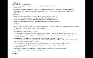
BPEL - Partner Links
•Give details on the relationship between the BPEL process and each partner service
<partnerlinks>
<partnerlink name="ProcessQuote" partnerlinktype="ProcessQuotePLT" myrole="ProcessQuoteRole">
<partnerlink name="mainframeQuoteMgr" partnerrole="partnerRole" partnerlinktype="PartnerLinkPLT">
</partnerlinks>
BPEL - Variables
•assigns variables, which are memory areas that are each described by a Web Services Description Language (WSDL) message but could have been described by an XML Schema element or type
<variables>
<variable name="quoteRequest" messageType="placeQuoteRequestMsg" />
<variable name="highlightQuote" messageType="placeQuoteResponseMsg" />
<variable name="buildQuoteReq" messageType="buildQuoteRequestMsg" />
<variable name="newHighlightQuote" messageType="buildQuoteResponseMsg" />
</variables>
BPEL - Quote Request
receives a quote request
<receive name="processQuoteRequest" createInstance="yes" operation="placeQuote" partnerLink="ProcessQuote"
portType="ProcessQuote" variable="quoteRequest">
</receive>
BPEL - Copy Data
uses XPath syntax to copy data from the received message to a variable that is used for invoking another service
<assign name="AssignQuoteReq"> <copy>
<from variable="quoteRequest" part="placeQuoteParameters"> <query>/quoteInformation</query> </from>
<to variable="buildQuoteReq" part="buildQuoteParameters"> <query>/customerQuoteInfo</query></to>
</copy> </assign>
BPEL - Other Service
•invokes the other service, which calculates and returns a quote
<invoke name="CalculateQuote" inputVariable="buildQuoteReq" operation="buildQuote" outputVariable="newHighlightQuote" partnerLink="mainframeQuoteMgr" portType="QuoteManagement" />
BPEL - Copy to response
copies the quote details to another variable and in this way formats the response message
<assign name="AssignQuoteRes"> <copy>
<from variable="newHighlightQuote" part="buildQuoteResult"> <query>/quote</query> </from>
<to variable="highlightQuote" part="placeQuoteResult" > <query>/quote</query> </to>
</copy> </assign>
BPEL - Reply
•replies to the invoker, which may have been a Web application or a service
<reply name="processQuoteResponse" operation="placeQuote" partnerLink="ProcessQuote" portType="ProcessQuote" variable="highlightQuote" />
BPEL – General activities
•Run in a preset sequence
•Run in a loop
•Run on condition that a Boolean expression evaluates to true
•Run immediately or wait for some period of time, even years
•Run in response to an event that occurs after the process starts (specifically, in response to an inbound message, a calendar date and clock time, or the passing of time)
•Run in an order that differs for different instances of the same process
BPEL – Processes
•BPEL executable process – a Web service and acts as the hub in a service orchestration
•Software that runs an executable process is called a BPEL engine
•BPEL abstract process – similar to BPEL executable process but includes a subset of the information. It is a description of business logic, it omits implementation details in most cases
BPEL – WSDL
•PartnerLinkType – specifies the roles between the BPEL process and a partner service. (BPEL, WSDL)
•Port Type – WSDL
•Operations – WSDL
•Data types – XSD
BPEL – WSDL-based constructs
•Properties and property aliases benefits
•Use same name to access the same data in differently structured variables
•Name’s position change doesn’t necessarily change the logic in BPEL process
•BPEL correlation set (constants). Help direct an inbound message to the correct instance of BPEL process
BPEL – Process Elements
<process>
<import> </import>
<partnerLinks> </partnerLinks>
<messageExchanges> </messageExchanges>
<variables> </variables>
<correlationSets> </correlationSets>
<faultHandlers> </faultHandlers>
<eventHandlers> </eventHandlers>
<!— The previous two elements include activities, as does the subsequent content of the process element. Activities can be enclosed in scopes, as described later. —>
</process>
BPEL – File Structure
•Import - provides access to a WSDL definition or an XML Schema
•Partner link - is a kind of specialized variable that describes the relationship between the BPEL process and a partner service
•Message exchange - is an idnetifier that is used to avoid an ambiguous case in a complex usiness scenario – specifically, to pair a BPEL activity that receives a message with the activity that issues a reply
•Variable - contains business data (message, process logic)
•Correlation set – listing of properties used to correlate service instances
•Fault handler – a set of activities that run in response to a fault (failure in the process)
•Event handler – a set of activities that run concurrently with other activities, in response either to the passage of time or to receipt of a message
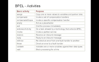
BPEL – Partner Link
•myRole – enacted by the BPEL process
•Operations are described in port type that is related to the role.
•partnerRole – enacted by the partner service
•Multiple partner links can be based on the same partner link type.
BPEL – Correlation Sets
•Maintain data integrity
•A list of propertirs whose values are expected to remain constant throughout a process or throughout a specific scope
•Reference only in activities that receive or transmit data
•Inbound activity – BPEL engine to direct msg
•Outbound activity – verify property values
•Inboundor outbound – initiates the correlation set
BPEL – Fault Handling
•Purpose – minimize the effect of an error
•Composed of a catch or optional catchAll
•Each fault handler hasselection criteria, which include (optionally) the fault name and the type of data
•BPEL engine selects the fault handler whose selection criteria most closely mirror the fault
•If the fault has a name but no data, BPEL engine selects the fault handler whose selection criteria match exactly
•If no catchAll, BPEL provides default:
<catchAll>
<sequence>
<compensate/>
<rethrow/>
</sequence>
</catchAll>
BPEL – Compensation Handling
•Compensation for a successfully completed scope occurs under the guidance of a compensation handler
•Invocation always comes from a parent scope
•The compensateScope activity invodes the compensation handler of a specific nested scope
•A failure in scope A causes invocation of the compensation handler in scope B:
<scope name="A">
<compensationHandler>
<compensateScope target="B">
</compensationHandler>
<scope name="B">
<compensationHandler>
<!— a basic or structured activity is here —>
</compensationHandler>
</scope>
</scope>
BPEL – Termination Handling
•Set of activities that are issues when a running scope is being forced to terminate
•Default
<terminationHandler >
<compensate/>
</terminationHandler>
BPEL - Concurrency
Synchronized - Activities run concurrently and one activity is forced to wait for another
BPEL Activity – Start
•First activity (other than flow, scope or sequence)
•1. a receive activity
•2. a pick activity that contains only onMessage events
•Open Standards
•Structure of a SOA Application – composed largely of services (Integration Services, Business Services, Data-Access Services)
•Web and Binary-Exchange Services – WSDL, SOAP, HTTP
•Presentation Services – Portlet, HTML,
•Runtime Products – security, service allocation, service composition, logging
•Loose Coupling
•Service Registry
•Service Level Agreements
Service Aspects
•Service Implementation - Logic
•Elementary access details – Location, binding, protocol, formatting
•Contract – interface and Quality of Service
Message Exchange Patterns
•One-way pattern – (fire-and-forget)
•Request-response pattern – (in-out)
•Notification pattern – (out-only)
•Solicit-response pattern – (out-in)
•Synchronous and Asynchronous Communication
•Callbacks – (Request and callback)
Quality of Service
•Reliability guarantees- availability, throughput, response time and probability, assured message
•Security mechanisms – Authentication, authorization, confidentiality, integrity, non-repudiation, attack protection
•Service coordination, including transaction control – Orchestration, Choreography
•Runtime update of address, binding, and message content – flow of traffic change, message reformat, send message to destination other than the requester
Process Steps
•Analyzing a Business Process
•Identifying Problems with current Process
•Communicating the Assumptions in Writing
•Isolating Services
•Creating the application
XML Schema
•Data Type – primitive, derived, simple, complex
•Purposes – data exchange, validation rules
•Groups, Sequencing,
SOA Standards
•WSDL
•SOAP
•UDDI

Introduction to BPEL
•BPEL process fulfills a workflow by accessing one service after another (partner service)
•BPEL activity is equivalent to a function call
•Running time can be far longer than other kinds of software
•Mechanisms for fault handling, compensation, correlation
•BPEL abstract process – subset of BPEL executable process (no implementation)
Additional language used by BPEL
•Query Language – XPath
•Expression language – XPath, Java
•doXslTransform
•Can use WSDL as source of data types
•PartnerLinkType (WSDL) – runtime conversation to partner service
BPEL Basics
•Activities– assign,compensate,compensateScope, empty, exit, extensionActivity, invoke, receive, reply, rethrow, throw, validate, wait
• An XML-base language for creating a process
•1. Accept a request for an insurance quote
•2. If the submitted details are appropriate, calculate the quote and include it in the response
•3. Otherwise, say “No” and include a justfication

BPEL - Partner Links
•Give details on the relationship between the BPEL process and each partner service
<partnerlinks>
<partnerlink name="ProcessQuote" partnerlinktype="ProcessQuotePLT" myrole="ProcessQuoteRole">
<partnerlink name="mainframeQuoteMgr" partnerrole="partnerRole" partnerlinktype="PartnerLinkPLT">
</partnerlinks>
BPEL - Variables
•assigns variables, which are memory areas that are each described by a Web Services Description Language (WSDL) message but could have been described by an XML Schema element or type
<variables>
<variable name="quoteRequest" messageType="placeQuoteRequestMsg" />
<variable name="highlightQuote" messageType="placeQuoteResponseMsg" />
<variable name="buildQuoteReq" messageType="buildQuoteRequestMsg" />
<variable name="newHighlightQuote" messageType="buildQuoteResponseMsg" />
</variables>
BPEL - Quote Request
receives a quote request
<receive name="processQuoteRequest" createInstance="yes" operation="placeQuote" partnerLink="ProcessQuote"
portType="ProcessQuote" variable="quoteRequest">
</receive>
BPEL - Copy Data
uses XPath syntax to copy data from the received message to a variable that is used for invoking another service
<assign name="AssignQuoteReq"> <copy>
<from variable="quoteRequest" part="placeQuoteParameters"> <query>/quoteInformation</query> </from>
<to variable="buildQuoteReq" part="buildQuoteParameters"> <query>/customerQuoteInfo</query></to>
</copy> </assign>
BPEL - Other Service
•invokes the other service, which calculates and returns a quote
<invoke name="CalculateQuote" inputVariable="buildQuoteReq" operation="buildQuote" outputVariable="newHighlightQuote" partnerLink="mainframeQuoteMgr" portType="QuoteManagement" />
BPEL - Copy to response
copies the quote details to another variable and in this way formats the response message
<assign name="AssignQuoteRes"> <copy>
<from variable="newHighlightQuote" part="buildQuoteResult"> <query>/quote</query> </from>
<to variable="highlightQuote" part="placeQuoteResult" > <query>/quote</query> </to>
</copy> </assign>
BPEL - Reply
•replies to the invoker, which may have been a Web application or a service
<reply name="processQuoteResponse" operation="placeQuote" partnerLink="ProcessQuote" portType="ProcessQuote" variable="highlightQuote" />
BPEL – General activities
•Run in a preset sequence
•Run in a loop
•Run on condition that a Boolean expression evaluates to true
•Run immediately or wait for some period of time, even years
•Run in response to an event that occurs after the process starts (specifically, in response to an inbound message, a calendar date and clock time, or the passing of time)
•Run in an order that differs for different instances of the same process
BPEL – Processes
•BPEL executable process – a Web service and acts as the hub in a service orchestration
•Software that runs an executable process is called a BPEL engine
•BPEL abstract process – similar to BPEL executable process but includes a subset of the information. It is a description of business logic, it omits implementation details in most cases
BPEL – WSDL
•PartnerLinkType – specifies the roles between the BPEL process and a partner service. (BPEL, WSDL)
•Port Type – WSDL
•Operations – WSDL
•Data types – XSD
BPEL – WSDL-based constructs
•Properties and property aliases benefits
•Use same name to access the same data in differently structured variables
•Name’s position change doesn’t necessarily change the logic in BPEL process
•BPEL correlation set (constants). Help direct an inbound message to the correct instance of BPEL process
BPEL – Process Elements
<process>
<import> </import>
<partnerLinks> </partnerLinks>
<messageExchanges> </messageExchanges>
<variables> </variables>
<correlationSets> </correlationSets>
<faultHandlers> </faultHandlers>
<eventHandlers> </eventHandlers>
<!— The previous two elements include activities, as does the subsequent content of the process element. Activities can be enclosed in scopes, as described later. —>
</process>
BPEL – File Structure
•Import - provides access to a WSDL definition or an XML Schema
•Partner link - is a kind of specialized variable that describes the relationship between the BPEL process and a partner service
•Message exchange - is an idnetifier that is used to avoid an ambiguous case in a complex usiness scenario – specifically, to pair a BPEL activity that receives a message with the activity that issues a reply
•Variable - contains business data (message, process logic)
•Correlation set – listing of properties used to correlate service instances
•Fault handler – a set of activities that run in response to a fault (failure in the process)
•Event handler – a set of activities that run concurrently with other activities, in response either to the passage of time or to receipt of a message

BPEL – Partner Link
•myRole – enacted by the BPEL process
•Operations are described in port type that is related to the role.
•partnerRole – enacted by the partner service
•Multiple partner links can be based on the same partner link type.
BPEL – Correlation Sets
•Maintain data integrity
•A list of propertirs whose values are expected to remain constant throughout a process or throughout a specific scope
•Reference only in activities that receive or transmit data
•Inbound activity – BPEL engine to direct msg
•Outbound activity – verify property values
•Inboundor outbound – initiates the correlation set
BPEL – Fault Handling
•Purpose – minimize the effect of an error
•Composed of a catch or optional catchAll
•Each fault handler hasselection criteria, which include (optionally) the fault name and the type of data
•BPEL engine selects the fault handler whose selection criteria most closely mirror the fault
•If the fault has a name but no data, BPEL engine selects the fault handler whose selection criteria match exactly
•If no catchAll, BPEL provides default:
<catchAll>
<sequence>
<compensate/>
<rethrow/>
</sequence>
</catchAll>
BPEL – Compensation Handling
•Compensation for a successfully completed scope occurs under the guidance of a compensation handler
•Invocation always comes from a parent scope
•The compensateScope activity invodes the compensation handler of a specific nested scope
•A failure in scope A causes invocation of the compensation handler in scope B:
<scope name="A">
<compensationHandler>
<compensateScope target="B">
</compensationHandler>
<scope name="B">
<compensationHandler>
<!— a basic or structured activity is here —>
</compensationHandler>
</scope>
</scope>
BPEL – Termination Handling
•Set of activities that are issues when a running scope is being forced to terminate
•Default
<terminationHandler >
<compensate/>
</terminationHandler>
BPEL - Concurrency
Synchronized - Activities run concurrently and one activity is forced to wait for another
BPEL Activity – Start
•First activity (other than flow, scope or sequence)
•1. a receive activity
•2. a pick activity that contains only onMessage events
Oracle Application Server 10g Corporate Portal
Overview
•Browser-based environment for building, deploying, and maintaining enterprise portals
•Secure and manageable framework
•Organized and personalized views
•Self-service Web publishing
•Manageable deployment architecture
Oracle Application Server Components
•Oracle Internet Directory (OID)
•OracleAS Portal (OC4J)
•OracleAS Wireless
•OracleAS Web Cache
•OracleAS Personalization
•OracleAS Integration
Grid Computing
Architecture that pools large numbers of servers and storage into a less expensive, flexible, on-demand computing resource for all enterprise needs
- Standardize low cost components
- Consolidate shared resources
- Automate management operations
OracleAS 10g portal Solution
•Content management (Classify content, Navigate and access content; Route content for review and approval)
•Content display (Create, organize, and manage pages; Build and customize dynamic portlets
•Content integration (integrate applications and disparate data by using built-in functionality, including Web Clipplig, OmmiPortlet, and Portlet Builder
Major User Roles in OracleAS Portal

- Page designers
- Content contributors and content managers
- Portlet developers
- Portlet developers
- Portal administrator
Portal Page Modes

Portal Page Modes

•Page group – Root page; Subpages
•View mode; Graphical mode; Layout mode; List mode
Adding Content to Portal
Item
•An item is a basic unit of content on a portal page.
•Two kinds –
•Content item type
•Navigation item type
Content item types
•File and Simple File
•Simple Image
•Image and Simple Image Map
•PL/SQL and Simple PL/SQL
•Prge Link and Simple Page Link
•Text and Simple Text
•URL and Simple URL
•Zip File
Item-Related Features
•Versioning
•Item-level security
•Document control
•Publishing dates
•Expiry dates
•Approvals
Adding Items

Accessing the Document Library by Using a WebDAV Client
With a WebDAV client, you can:
- Move content, files, and folders between your desktop and the document library
- Open, edit, and save file type items "in place" by using desktop application
Content Metadata
•Data about the content in the document library
•Set explicitly or implicitly
•Made up of three main components (Attributes; Categories; Perspectives)
Classifying Content in OracleAS Portal
•Category – A predefined attribute that is used to group or classify pages, items, and portlets
•Data about the content in the document library
•Set explicitly or implicitly
•Made up of three main components (Attributes; Categories; Perspectives)
Classifying Content in OracleAS Portal
•Category – A predefined attribute that is used to group or classify pages, items, and portlets
Creating Category

•Perspective – A cross-category grouping of items and pages (attributes)
- Further classify content across categories
- Enable users to view related content classified in different categories
Creating Perspectives

Implementing Custom Types
Custom Types
•Custom types are unique types you create to extende the standard type definitions provided by OracleAS Protal.
•Custom attributes – User-defined attributes based on predefined data types created to store additional info about an item. (used in definition of custom item types and page types)
•Custom item types
•Custom page types
•[Item Type]n-n[Attribute]n-n[page type]
Creating Custom Item Types

Approval Process
A Series of one or more approval routing steps
- Each step must have one or more approvers
- Routing to approvers can be in serial or in parallel
Portal Page

•OracleAS Protal object that contains portlets and items.
•A portal page is the face of the portal – that which the user interacts with to access informatipn and applications. The layout of a portal page is defined through regions
•A portal page combines the features of a directory folder and a browser page.Like a folder, a page can exist within a hierarchy of pages and can contain content.
Page Group
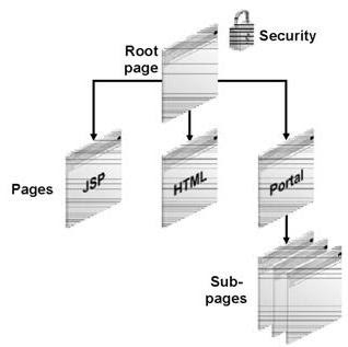

•A page group is a hierarchical collection of pages for which common attributes and mechanisms can be established to govern the behavior of the pages it contains.
•Consider – (Administering page groups; Managing content metadata; managing content presentation; Copying and moving content)
•Region – rectanglar area on a page used to define the page layout (Types: Item; Portlet; Sub-Page Links; Undefined)
Shared Objects
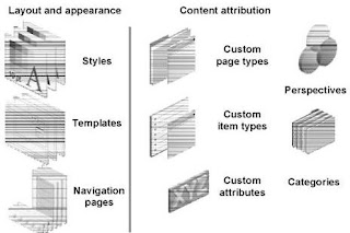
•Consider – (Administering page groups; Managing content metadata; managing content presentation; Copying and moving content)
•Region – rectanglar area on a page used to define the page layout (Types: Item; Portlet; Sub-Page Links; Undefined)
Shared Objects

•Layout and appearance (Styles; Templates; Navigation pages)
•Content attribution (Custom page types; Custom item types; Custom attributes; Perspectives; Categories
Style
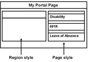
•Content attribution (Custom page types; Custom item types; Custom attributes; Perspectives; Categories
Style

•Set of values and parameters that controls the colors and fonts that are used by pages and regions within a page
Page template
•An object that enforces an standard layout and appearance for multiple pages
Page template
•An object that enforces an standard layout and appearance for multiple pages
Navigation Items
•Portal Smart Link
•Login/Logout Link
•Basic Search Box
•List of Objects
•Portal Smart Text
•Object Map Link
•Page Path
•Page Function
Page parameters
•Synchronize portlets residing on a page
•Enable the reuse of portlets on multiple pages with no additional coding
•Provide users the means to customize pages based on their input values
Portlet parameters
•Enable the portlet developer to declare a public data input interface for the page designer to use
•Give the page designer control over the input data to the portlet
Integrating Page and Portlet Parameters

Controlling Access to Page Groups

Controlling Access to Pages


Item-Level Privileges
•Manage
•Edit
•View
Accessing Portal Objects by Using Direct Access URLs

Web Clippling
A piece of existing Web content that can be repurposed in other Web pages, particularly portals.
OmniPortlet
A feature of Oracle AS Portal that enables you to quickly and easily publish data from various data sources and render the result in a variety of formats.
Supported data sources
•Spreadsheet
•SQL
•XML
•Web Service
•Web Page
Supported Data formates
•Tabular
•Chart
•News layout
•Bulleted list
•Form
Data-Driven Portlets (DB, SQL etc)
OracleAS Portal Forms
•Forms based on tables and views
•Master-detail forms based on two tables or views
•Forms based on stored procedures
OracleAS Poprtal Reports
Publishing Business Intelligence on a Portal Page

OrcleAS Discoverer provides two types of portlets
•List of Database Workbooks portlet: Contains the names and links to Discoverer workbooks
•Worksheets portlet: Enables you to place actual worksheetcontent on the portal page
Privileges
- Global privileges
- Objectr-level Privileges- The corresponding global privilege overrides an object-level privilege
Service Oriented Enterprise (SOA)
Technical Foundation
1. ESB
2. Organizational Commitment to BPM
3. Enterprise Performance Management (EPM)
Three essential layers
1. Enterprise performance layer
2. Business process management layer
3. Service Oriented Architecture infrastructure
EPM - Focuses on specifying the strategic key performance indicators of the service enterprise and typing these to underlying business processes and policies
BPM – Utilize the infrastructure services provided b y service oriented architecture
ESB – Provides a common standards services-based brokering container
BPM
- Bring IT and businesses together and narrow, and sometimes eliminate, the IT-business divide.
- Allow enterprises to separate business processes and business rules to model and to manage them independently of applications
Three layers of service oriented enterprises
- Service Performance (Enterprise Performance Management)
- Service Integration (Business Process Management)
- IT Service Infrastructure (Service Oriented Architecture)
- Process-Oriented Culture (In service oriented enterprises products are processes)
What are strategies?
- Mission: A concise statement of the organization’s reason for existing
- Objectives: Broad statements describing the targeted direction
- Goals: Quantifications of objectives for a designated period of time
- Strategies: Statements of how objectives will be achieved and the major methods to be used
- Tactics: Specific action steps that map out how each strategy will be implemented
- KPIs: Measures of performance that show progress of each tactic in reaching the goals
Three Phases of SOEs
Phase 1: Point-to-point Enterprise Integration Focused (WSDL + SOAP)
Phase 2: Orchestration ESB, BPMS, Public Service Interface, Initial OoS Focus: WS-Security and Reliability, Initial Service Mgmt, Robust UDDI Deployments
Phase 3: Federated ESBs/BPMSs, Performance Mgmt of Service Application, End ot End Service Integration, B2B Process, Dynamic Discovery and Binding, Software as Service
Process Standardization
Notation – UML: OMG; BPMN: OMG
Process Definition / Execution – BPEL: OASIS; XPDL: WfMC; WS-CDL: W3C; ebXML BPSS; RosettaNet RNIF
Process Engine / Interoperability – Wf-XML: WfMC; BPSI: OMG
Business Process Management – Business process activity monitoring and performance capabilities
Business Performance Management- addition include monitoring and analysis of applications (BP, ERP, CRM, ect)
Wednesday, March 25, 2009
WS-BPEL 2.0
•WS-BPEL: XML based programming language to describe high level business processes
•Web Service: using Web Service Description Language (WSDL)
BPEL Servers and Engine
•Create on demand
•BPEL engine: Focus to act as an execution engine which can be programmed using BPEL
BPEL Programming Language
•Programming logic – BPEL
•Data Types – XSD (XML Schema Definition)
•Input/Output (I/O) – WSDL (Web Services Description Language)
http://schemas.xmlsoap.org/ws/2003/03/business-process/" xmlns:print="http://www.eclipse.org/wsws/choreography/2004/engine/Print">
http://schemas.xmlsoap.org/wsdl/" location="../../test_bucket/service_libraries/wsws_EnginePrinterPort.wsdl" namespace="http://www.eclipse.org/wsws/choreography/2004/engine/Print" /> Hello World $hello_world.value
Importing WSDL and XSD files
•The 'import' statement in BPEL is a directive to import a WSDL or XSD file. Importing XSD files allows commonly used datatypes or datatypes required for a particular endpoint (thing that you speak to) to be defined in a file separate to the BPEL file. Importing WSDL files allows endpoint descriptions (definitions of things that you speak to) to be defined in files separate to the BPEL file.
Partner Link
•Partner Links can be thought of as placeholders for things that you actually speak to. A web service is described in full by the WSDL files that specify it but Partner Links allow you to have something like an instance of the web service that you speak to. A partner link basically maps to a WSDL web service 'portType', so one partnerLink (e.g. 'printService' above) maps to a single web service.
•However, partner links don't just describe what you speak to, they also can describe how other web service clients speak to you. In the partner link definition above, a 'partnerRole' attribute defines the web service that this BPEL process will speak to. Alternatively, the partner link could have a 'myRole' attribute which would define a web service that this BPEL process implements.
Variable definition
•Variables are used to contain data in BPEL. A variable can either contain an XSD value or a WSDL message. In the example above, a variable called 'hello_world' is declared as a container for WSDL messages of type 'print:PrintMessage'. Instead of the 'messageType' attribute, the variable could have had a 'type' attribute which would specify some xsd simple or complex type like 'xsd:string' or 'xsd:integer'.
•Variables are used to pass data in and out of web service endpoints.
Variable assignment
•Variables are manipulated in BPEL either through use via web service endpoints or by assignment. The example above shows a literal string value being assigned into the variable 'hello_world'. The variable 'hello_world' in this case is a WSDL message with a part called 'value'. The part called 'value' is an 'xsd:string' type. It can therefore have other 'xsd:string's assigned into it, including literal strings.
•The '$varname' syntax used to reference the variable here is standard XPATH expression syntax. The '.' separator is used to specify the WSDL message part. If the variable or the part were an XSD complex type then a '/' separator could be used to specify the sub-element within the complex type (e.g. '$hello_world.value/subvalue').
Web Service Invocation
•The 'invoke' activity in BPEL invokes a web service endpoint. This is where the BPEL process passes the 'Hello World' data (stored in the 'hello_world' variable) to the 'print' web service. The specified partnerLink tells the BPEL engine the address of the web service you want to invoke here. The 'print' operation specifies what you actually want the web service to do and the 'inputVariable' specifies that the input WSDL message should come from the 'hello_world' variable.
•What the web service actually does and exactly how the web service is implemented is not referenced in BPEL at all - all the implementation and definition information is contained within the defining WSDL file.
Web Service (in Java) - WSDL
http://schemas.xmlsoap.org/wsdl/" targetNamespace="http://www.eclipse.org/wsws/choreography/2004/engine/Print" xmlns:tns="http://www.eclipse.org/wsws/choreography/2004/engine/Print" xmlns:xsd="http://www.w3.org/2001/XMLSchema" xmlns:wsdl="http://schemas.xmlsoap.org/wsdl/" xmlns:format="http://schemas.xmlsoap.org/wsdl/formatbinding/" xmlns:java="http://schemas.xmlsoap.org/wsdl/java/" >
WSDL Messages
•WSDL messages are used to specify what the containers should be like that hold data when a WSDL operation is invoked. They are essentially lists of parts, each of which is an XSD simple or complex type.
•In the example above the 'PrintMessage' is defined as having a single part 'value', which is of type 'xsd:string'.
WSDL Port Types
•WSDL Port Types represent the definition of the web service itself. They describe the API or interface to the web service. A port type is a list of operations with 'input's and 'output's. Each of the 'input's and 'output's is a WSDL message that must have been previously defined (although it could have been imported from another WSDL file).
•A WSDL port type operation can also have any number of 'fault' elements. Each of these specifies an error message which would be an alternative to the 'output' message.
•Note that the name specified on the port type does not have any namespace prefix. This is because the port type is being defined here and now and it will inherit the target namespace. The 'printMessage' specified in the operation definition however DOES have a namespace prefix. This is because the printMessage has previously been defined and is being referenced. The 'tns:' prefix maps to the same namespace as the target namespace in the previously defined 'printMessage' message.
WSDL Port Type Bindings
•A 'binding' in WSDL specifies how the web service is actually implemented. Everything up until this point has been abstract and has dealt with only how to speak to the web service. The binding specifies what is on the other side that you are speaking to.
•A web service can be bound in many different ways. The most common bindings for a web service are: oas a SOAP/HTTP web service - whereby some implementation would be listening on a specified port and would accept SOAP messages over an HTTP transport. oas a Java web service - whereby some java class is mapped to the port type and is used directly as an implementation.
•In the binding above, a mapping has been created which specifies that the port type operation 'print' should be mapped to a Java method called 'print'. In addition to this, the XSD type 'string' has been mapped to the Java type 'String'.
•Using this mapping information a Java class can be specified later in the WSDL file as the 'address' of a concrete web service implementation. This class can be instantiated and when calls are made to the 'print' operation, they will be proxied to the 'print' method of this class. In the process of proxying the 'print' operation, any XSD strings will also be converted to Java strings as specified in the binding.
WSDL Service
•The WSDL 'service' element specifies a WSDL 'port'. A single port is an instance of a web service, which is implemented via a particular binding and which is available at a given address.
•In the case of our printout port, we are defining a web service which is bound using the previously defined Java binding and which can be found at the address 'org.eclipse...EnginePrinterPort‘.
•Note that the address is binding specific. The Java binding knows to interpret the 'className' attribute as a fully qualified Java class name and understands how to instantiate the class and proxy the WSDL operations to the Java methods specified in the 'binding' element.
Partner Link Types
•Partner Link Types are actually not a WSDL construct, but a BPEL construct. WSDL was around before BPEL and is purely designed towards describing web services. BPEL however requires that a partner link instance be associated with a particular WSDL port type. In this case there is only one end of the partner link which needs to be implemented - the 'printService' role. It is possible to have two roles in a single partner link type, each of which can be implemented by two communicating web services.
•The BPEL partnerLink definition specified a partner link type for the partner link and also either a 'myRole' or a 'partnerRole'. In our previous example the 'partnerRole' was defined as 'printService'. This is because the BPEL process will be speaking TO the 'printService', rather than acting as a 'printService' which other web clients can speak to (in that case the 'myRole' part of the partner link would have been defined).
Java Web Service Implementation
package org.eclipse.wsws.choreography.jengine.internal.extensions.wsdlbinding.wsif.ports; public class EnginePrinterPort { public void print(String s) { System.out.println(s); } }
The Java class specified in the WSDL 'service' element is the Java class that the BPEL engine will expect to find at runtime. We therefore need to create that java class and fill it with any methods that we specified mappings to in the WSDL 'binding' element (e.g. the 'print' method).
Deploying web service
•Once you have your BPEL file using the WSDL web service description you created and you have your compiled Java class that implements the web service you need to put it all together.
•The quickest and easiest way to do this is to use the 'Dependencies' tab in the Choreography launch configuration.
•Set up a launch configuration to run your Hello World BPEL file and then click on the 'Dependencies' tab. In here you can tell the engine which JARs are required for any user-provided java endpoints. Just click 'Add' and then choose the JAR containing your Hello World Java web service implementation. You should see the JAR show up in the table and you should ensure that the JAR is set to 'enabled'.
•Once you've added the dependency, just run the launch configuration. If you're running a distributed engine the engine will automatically pass the dependency JAR around for use on remote engines (engines on other host machines).
Redistributable Java Endpoint Deployment (Deploying as an Eclipse Plugin)
•If you want to write a Java web service implementation or build up a library of useful services that you want to be able to distribute or send to other people then you can expose dependencies via the Eclipse Extension Point mechanism.
•Just extend the extension point 'org.eclipse.wsws.choreography.internal_WSDLPortDependency' and add a reference to your JAR. The 'namespace' attributes specify which namespaces your JAR is required for. If any of the specified namespaces are used your JAR will be passed round the engine in anticipation of use by the BPEL program.
http://www.eclipse.org/wsws/choreography/2004/engine" />
•Web Service: using Web Service Description Language (WSDL)
BPEL Servers and Engine
•Create on demand
•BPEL engine: Focus to act as an execution engine which can be programmed using BPEL
BPEL Programming Language
•Programming logic – BPEL
•Data Types – XSD (XML Schema Definition)
•Input/Output (I/O) – WSDL (Web Services Description Language)
http://schemas.xmlsoap.org/ws/2003/03/business-process/" xmlns:print="http://www.eclipse.org/wsws/choreography/2004/engine/Print">
http://schemas.xmlsoap.org/wsdl/" location="../../test_bucket/service_libraries/wsws_EnginePrinterPort.wsdl" namespace="http://www.eclipse.org/wsws/choreography/2004/engine/Print" />
Importing WSDL and XSD files
•The 'import' statement in BPEL is a directive to import a WSDL or XSD file. Importing XSD files allows commonly used datatypes or datatypes required for a particular endpoint (thing that you speak to) to be defined in a file separate to the BPEL file. Importing WSDL files allows endpoint descriptions (definitions of things that you speak to) to be defined in files separate to the BPEL file.
Partner Link
•Partner Links can be thought of as placeholders for things that you actually speak to. A web service is described in full by the WSDL files that specify it but Partner Links allow you to have something like an instance of the web service that you speak to. A partner link basically maps to a WSDL web service 'portType', so one partnerLink (e.g. 'printService' above) maps to a single web service.
•However, partner links don't just describe what you speak to, they also can describe how other web service clients speak to you. In the partner link definition above, a 'partnerRole' attribute defines the web service that this BPEL process will speak to. Alternatively, the partner link could have a 'myRole' attribute which would define a web service that this BPEL process implements.
Variable definition
•Variables are used to contain data in BPEL. A variable can either contain an XSD value or a WSDL message. In the example above, a variable called 'hello_world' is declared as a container for WSDL messages of type 'print:PrintMessage'. Instead of the 'messageType' attribute, the variable could have had a 'type' attribute which would specify some xsd simple or complex type like 'xsd:string' or 'xsd:integer'.
•Variables are used to pass data in and out of web service endpoints.
Variable assignment
•Variables are manipulated in BPEL either through use via web service endpoints or by assignment. The example above shows a literal string value being assigned into the variable 'hello_world'. The variable 'hello_world' in this case is a WSDL message with a part called 'value'. The part called 'value' is an 'xsd:string' type. It can therefore have other 'xsd:string's assigned into it, including literal strings.
•The '$varname' syntax used to reference the variable here is standard XPATH expression syntax. The '.' separator is used to specify the WSDL message part. If the variable or the part were an XSD complex type then a '/' separator could be used to specify the sub-element within the complex type (e.g. '$hello_world.value/subvalue').
Web Service Invocation
•The 'invoke' activity in BPEL invokes a web service endpoint. This is where the BPEL process passes the 'Hello World' data (stored in the 'hello_world' variable) to the 'print' web service. The specified partnerLink tells the BPEL engine the address of the web service you want to invoke here. The 'print' operation specifies what you actually want the web service to do and the 'inputVariable' specifies that the input WSDL message should come from the 'hello_world' variable.
•What the web service actually does and exactly how the web service is implemented is not referenced in BPEL at all - all the implementation and definition information is contained within the defining WSDL file.
Web Service (in Java) - WSDL
http://schemas.xmlsoap.org/wsdl/" targetNamespace="http://www.eclipse.org/wsws/choreography/2004/engine/Print" xmlns:tns="http://www.eclipse.org/wsws/choreography/2004/engine/Print" xmlns:xsd="http://www.w3.org/2001/XMLSchema" xmlns:wsdl="http://schemas.xmlsoap.org/wsdl/" xmlns:format="http://schemas.xmlsoap.org/wsdl/formatbinding/" xmlns:java="http://schemas.xmlsoap.org/wsdl/java/" >
WSDL Messages
•WSDL messages are used to specify what the containers should be like that hold data when a WSDL operation is invoked. They are essentially lists of parts, each of which is an XSD simple or complex type.
•In the example above the 'PrintMessage' is defined as having a single part 'value', which is of type 'xsd:string'.
WSDL Port Types
•WSDL Port Types represent the definition of the web service itself. They describe the API or interface to the web service. A port type is a list of operations with 'input's and 'output's. Each of the 'input's and 'output's is a WSDL message that must have been previously defined (although it could have been imported from another WSDL file).
•A WSDL port type operation can also have any number of 'fault' elements. Each of these specifies an error message which would be an alternative to the 'output' message.
•Note that the name specified on the port type does not have any namespace prefix. This is because the port type is being defined here and now and it will inherit the target namespace. The 'printMessage' specified in the operation definition however DOES have a namespace prefix. This is because the printMessage has previously been defined and is being referenced. The 'tns:' prefix maps to the same namespace as the target namespace in the previously defined 'printMessage' message.
WSDL Port Type Bindings
•A 'binding' in WSDL specifies how the web service is actually implemented. Everything up until this point has been abstract and has dealt with only how to speak to the web service. The binding specifies what is on the other side that you are speaking to.
•A web service can be bound in many different ways. The most common bindings for a web service are: oas a SOAP/HTTP web service - whereby some implementation would be listening on a specified port and would accept SOAP messages over an HTTP transport. oas a Java web service - whereby some java class is mapped to the port type and is used directly as an implementation.
•In the binding above, a mapping has been created which specifies that the port type operation 'print' should be mapped to a Java method called 'print'. In addition to this, the XSD type 'string' has been mapped to the Java type 'String'.
•Using this mapping information a Java class can be specified later in the WSDL file as the 'address' of a concrete web service implementation. This class can be instantiated and when calls are made to the 'print' operation, they will be proxied to the 'print' method of this class. In the process of proxying the 'print' operation, any XSD strings will also be converted to Java strings as specified in the binding.
WSDL Service
•The WSDL 'service' element specifies a WSDL 'port'. A single port is an instance of a web service, which is implemented via a particular binding and which is available at a given address.
•In the case of our printout port, we are defining a web service which is bound using the previously defined Java binding and which can be found at the address 'org.eclipse...EnginePrinterPort‘.
•Note that the address is binding specific. The Java binding knows to interpret the 'className' attribute as a fully qualified Java class name and understands how to instantiate the class and proxy the WSDL operations to the Java methods specified in the 'binding' element.
Partner Link Types
•Partner Link Types are actually not a WSDL construct, but a BPEL construct. WSDL was around before BPEL and is purely designed towards describing web services. BPEL however requires that a partner link instance be associated with a particular WSDL port type. In this case there is only one end of the partner link which needs to be implemented - the 'printService' role. It is possible to have two roles in a single partner link type, each of which can be implemented by two communicating web services.
•The BPEL partnerLink definition specified a partner link type for the partner link and also either a 'myRole' or a 'partnerRole'. In our previous example the 'partnerRole' was defined as 'printService'. This is because the BPEL process will be speaking TO the 'printService', rather than acting as a 'printService' which other web clients can speak to (in that case the 'myRole' part of the partner link would have been defined).
Java Web Service Implementation
package org.eclipse.wsws.choreography.jengine.internal.extensions.wsdlbinding.wsif.ports; public class EnginePrinterPort { public void print(String s) { System.out.println(s); } }
The Java class specified in the WSDL 'service' element is the Java class that the BPEL engine will expect to find at runtime. We therefore need to create that java class and fill it with any methods that we specified mappings to in the WSDL 'binding' element (e.g. the 'print' method).
Deploying web service
•Once you have your BPEL file using the WSDL web service description you created and you have your compiled Java class that implements the web service you need to put it all together.
•The quickest and easiest way to do this is to use the 'Dependencies' tab in the Choreography launch configuration.
•Set up a launch configuration to run your Hello World BPEL file and then click on the 'Dependencies' tab. In here you can tell the engine which JARs are required for any user-provided java endpoints. Just click 'Add' and then choose the JAR containing your Hello World Java web service implementation. You should see the JAR show up in the table and you should ensure that the JAR is set to 'enabled'.
•Once you've added the dependency, just run the launch configuration. If you're running a distributed engine the engine will automatically pass the dependency JAR around for use on remote engines (engines on other host machines).
Redistributable Java Endpoint Deployment (Deploying as an Eclipse Plugin)
•If you want to write a Java web service implementation or build up a library of useful services that you want to be able to distribute or send to other people then you can expose dependencies via the Eclipse Extension Point mechanism.
•Just extend the extension point 'org.eclipse.wsws.choreography.internal_WSDLPortDependency' and add a reference to your JAR. The 'namespace' attributes specify which namespaces your JAR is required for. If any of the specified namespaces are used your JAR will be passed round the engine in anticipation of use by the BPEL program.
Subscribe to:
Posts (Atom)


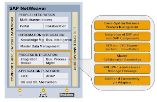